
Exploded View Prompts: Keeping the Parts Readable After They Come Apart
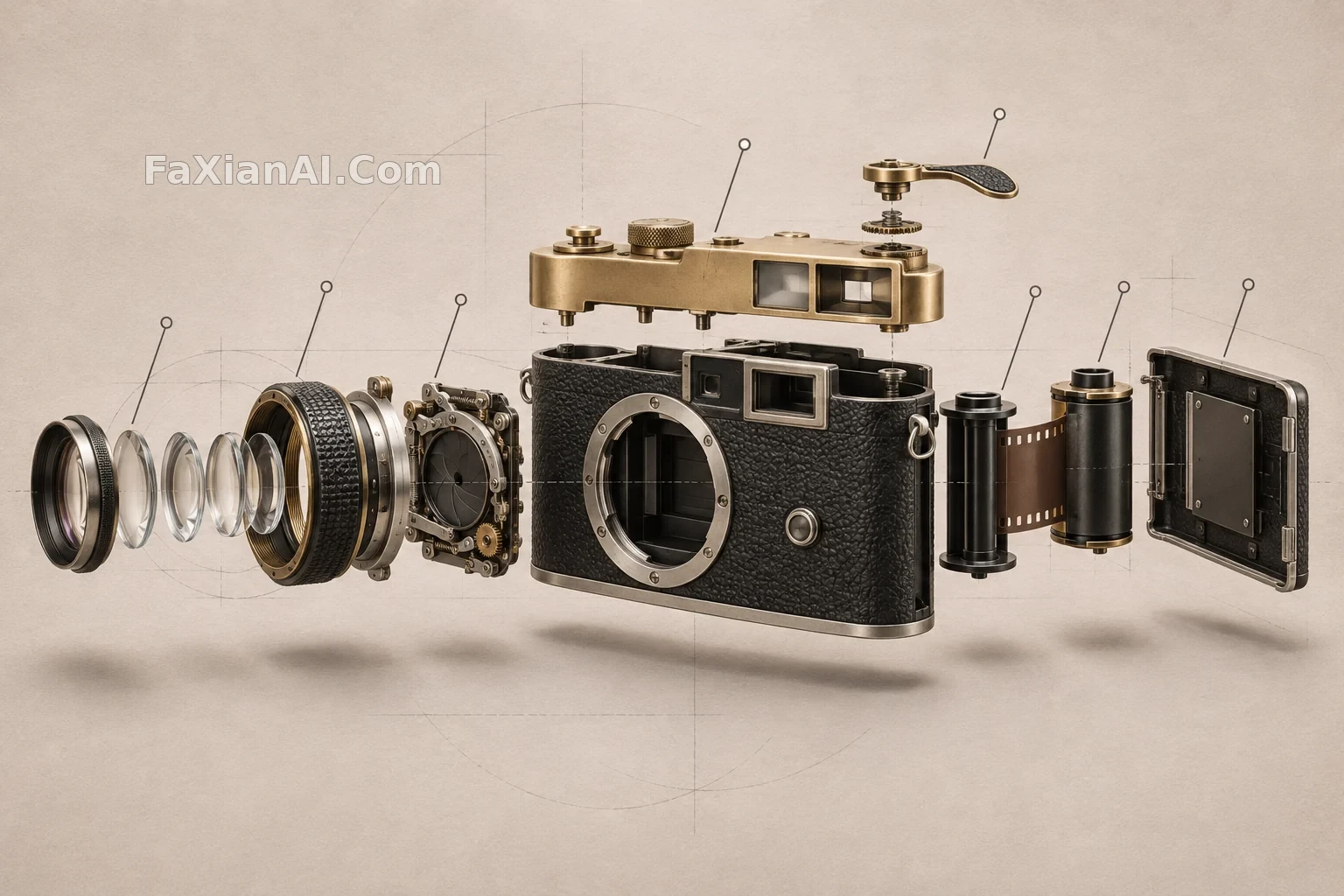
An exploded view prompt is easy to write: just ask the model to take something apart. The hard part is making it readable afterward: which direction should the parts move, what sits next to what, and how far apart should they be? Leave those things out and you’ll usually get a collection of attractive parts with no clear relationship to one another.
The exploded view examples on this site are all tackling roughly the same problem: making the relationships between parts visible.
Start With an Axis
In the prompt for the camera lens exploded along a single optical axis, the most important instruction is “all components coaxial.” A lens is built around an optical axis to begin with, so arranging the front ring, lens elements, aperture blades, focusing barrel, and mount along that line makes it natural to see how they fit back together.
The axis should suit the product’s structure. The six-layer magnesium laptop breakdown uses a vertical axis because a laptop is built in layers. The floating pebble chair breakdown also uses a vertical axis, with the cushion, bentwood frame, and foot pads arranged from top to bottom. The ceramic-white earbuds use a diagonal axis, which gives small objects a stronger sense of volume.
The camera at the top uses a horizontal axis, running from the lens to the rear cover and fitting neatly into the wide image. A useful rule of thumb: use a vertical axis for layered products, a horizontal axis for cylindrical ones, and a diagonal axis for small objects.
List Parts in Assembly Order
The parts list in the solar lantern exploded catalog image goes like this: lens, diffuser, LED ring, battery, sealing ring, folding handle. That’s the order in which the lantern comes apart, and the model largely follows it.
If the list is jumbled—battery first, then lens, then housing—the parts in the image may be jumbled too, with no clear way to put them back together. As you write the list, take the product apart in your head, from outside to inside or from front to back.
The robot dog joint module adds another constraint: “consistent nesting dimensions.” The housing, stator and rotor, reduction stages, and bearing rings fit inside one another. Get their relative sizes wrong and you can end up with a bearing larger than the housing. For cylindrical components, it’s worth adding that instruction.
Spacing and Shadows Make Parts Look Like They’re Floating
Leave out spacing and the model may cram the parts together or spread them so far apart that they look scattered. Both the lens and camping stove examples use the instructions “even gaps” and “subtle shadows beneath the components.” The shadows show how high the parts sit above the surface, helping establish the spacing.
Keep the background clean. Warm gray paper, pale ivory, and slate blue have all worked well. The key is a solid color without texture, so the outlines of the parts don’t get lost in the background.
To Label or Not to Label
Most examples specify “no text, numbers, or arrows.” The reason is practical: exploded view labels are small, and models easily turn small text into gibberish. They may also invent parameters that look professional. The earbuds and robot dog prompts add that the images “do not represent actual manufacturable engineering drawings,” to keep them from being mistaken for real specifications.
If you want the structure of labels without risking gibberish, take a cue from the camera at the top: draw the leader lines, but leave a small hollow circle at each end, as if reserving a place for someone to add text later.
A More Elaborate Breakdown
The complex machine split into three acrylic wedges skips the single axis. Instead, it divides the machine into three stages—frame, interior, and housing—and places them inside three acrylic wedges that fan outward. This is no longer a standard exploded view; it’s closer to a display installation. It works for a concept poster, but not for explaining a structure.
A Template You Can Adapt
> Industrial design exploded view of an original [product], against a [light warm gray paper / pale ivory] background. Components float along a [horizontal / vertical / diagonal] axis in assembly order: [outer components], [middle components], [internal components], [bottom components]. All components coaxial, evenly spaced, with consistent nesting dimensions and subtle shadows beneath each component. Photorealistic product rendering, soft overhead lighting. No text, numbers, arrows, logos, or branding.
Cutaways and exploded views are often discussed together, but they each have a different job: a cutaway shows the relationship between the inside and outside, while an exploded view shows assembly order. For cutaway prompts, see From Cutaway to Blueprint. For product materials and lighting, see Light and Materials in Product Photography. For details on the isometric perspective, see Isometric Perspective Prompts.